hid ballast wiring diagram [diagram] auto hid ballast wiring diagram
Understanding ballast wiring diagrams is crucial for anyone working with lighting systems, especially when dealing with metal halide and high-pressure sodium (HPS) lamps. These diagrams provide a visual representation of how the ballast, lamp, and power source should be connected to ensure proper and safe operation. Miswiring can lead to lamp failure, ballast damage, or even electrical hazards, making accurate interpretation of these diagrams paramount.
Philips Advance Metal Halide Ballast Wiring Diagram

This diagram illustrates the connections for a Philips Advance metal halide ballast. Metal halide lamps are known for their high efficiency and excellent color rendering, making them suitable for a wide range of applications, including street lighting, sports arenas, and retail spaces. The diagram will clearly show the line voltage input, often denoted as L1 and L2 (or Hot and Neutral), and the connections to the lamp socket. It's vital to note the voltage requirements of both the ballast and the lamp to ensure compatibility. Pay close attention to any grounding connections, typically indicated by a ground symbol. Incorrect grounding can compromise safety and affect the performance of the lighting system.
Furthermore, the diagram will specify the type of lamp the ballast is designed to operate. Metal halide lamps come in various wattages and configurations, and using the wrong ballast can result in premature lamp failure or even a hazardous situation. Some diagrams may also include information on capacitor connections, which are used to improve the power factor and reduce harmonic distortion. These capacitors are typically connected in parallel with the line voltage and must be rated appropriately for the voltage and frequency of the system. Always double-check the wiring diagram against the actual ballast and lamp being used to avoid errors. If you are unsure about any of the connections, consult with a qualified electrician or lighting specialist.
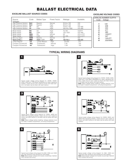
Additional Ballast Wiring Diagrams - HPS ballasts

This diagram provides examples of wiring configurations for High-Pressure Sodium (HPS) ballasts. HPS lamps are commonly used in outdoor lighting applications, such as roadways, parking lots, and security lighting, due to their high luminous efficacy and long lifespan. The diagram will show the connections between the ballast, ignitor (if required), lamp, and power source. HPS ballasts often require an ignitor to generate the high-voltage pulse needed to start the lamp. The ignitor is connected in series with the lamp and provides a brief, high-voltage surge that ionizes the gas inside the lamp, allowing it to strike. The wiring of the ignitor is critical for proper operation and must be done according to the diagram.
The line voltage input to the HPS ballast is typically indicated as L1 and L2, and the connections to the lamp socket will be clearly marked. It's essential to use the correct wire gauge and type for all connections, as HPS lamps can draw significant current. The diagram will also specify the type of HPS lamp the ballast is designed to operate. HPS lamps come in various wattages and configurations, and using the wrong ballast can result in lamp failure or even a fire hazard. Many HPS ballast wiring diagrams include information on the capacitor connections, which are used to improve the power factor and reduce harmonic distortion. These capacitors are typically connected in parallel with the line voltage and must be rated appropriately for the voltage and frequency of the system. Careful attention to detail when interpreting and implementing these wiring diagrams is crucial for ensuring safe and efficient operation of HPS lighting systems.
If you are searching about Hid Ballast Wiring Diagram Database you've came to the right page. We have 25 Images about Hid Ballast Wiring Diagram Database like Hella Hid Ballast Light Wiring Diagram, Harmonizing Your Vehicle With Hid Ballast Wiring Diagrams - Moo Wiring and also [DIAGRAM] Auto Hid Ballast Wiring Diagram - MYDIAGRAM.ONLINE. Read more:
Hid Ballast Wiring Diagram Database
 www.got2bwireless.com
 Hid Ballast Wiring Diagram
 simplecircuitwiringdiagrams.blogspot.com
 Universal Hid Ballast Wiring Diagrams
 diagramlibrarynuzzled.z19.web.core.windows.net
 Additional Ballast Wiring Diagrams - HPS Ballasts
hid.venturelighting.com wiring ballast diagram halide metal pulse hid start 1000w diagrams additional hps watt ignitor venturelighting
Harmonizing Your Vehicle With Hid Ballast Wiring Diagrams - Moo Wiring
 moowiring.com
 [DIAGRAM] Audi Hid Ballast Wiring Diagram 2002 - MYDIAGRAM.ONLINE
![[DIAGRAM] Audi Hid Ballast Wiring Diagram 2002 - MYDIAGRAM.ONLINE](https://cdn.shopify.com/s/files/1/0278/1997/products/qt2x54277_wire_1.jpeg?v%5C%5C%5C%5C%5C%5C%5C%5Cu003d1389626986) mydiagram.online
mydiagram.online Hid Light Ballast Wiring Diagram Internal
 manualsanctified.z14.web.core.windows.net
 Additional Ballast Wiring Diagrams - HPS Ballasts
 hid.venturelighting.com
 Hid Ballast Wiring Diagram
 simplecircuitwiringdiagrams.blogspot.com
 Philips Advance Metal Halide Ballast Wiring Diagram
www.circuitdiagram.co Hid Ballast Wiring Diagram
 diagrammanualadam.z13.web.core.windows.net
 Hid Ballast Wiring Diagram
 simplecircuitwiringdiagrams.blogspot.com
 150 Watt Hps Ballast Wiring Diagram
 diagramweb.net
 ballast wiring diagram halide watt vapor hps sodium mercury hid capacitor 400w m59 vapour temp 100c
Additional Ballast Wiring Diagrams - HPS Ballasts
 hid.venturelighting.com
 wiring c1 hid ballast hps venturelighting
Additional Ballast Wiring Diagrams - HPS Ballasts
 hid.venturelighting.com
 wiring ballast hid hps diagrams additional venturelighting
Additional Ballast Wiring Diagrams - HPS Ballasts
 hid.venturelighting.com
 wiring hid ballast
Hid Electronic Ballast Circuit Diagram - Circuit Diagram
 www.circuitdiagram.co
 Hid Ballast Wiring Diagram
 simplecircuitwiringdiagrams.blogspot.com
 Hid Electronic Ballast Circuit Diagram - Circuit Diagram
 www.circuitdiagram.co
 Harmonizing Your Vehicle With Hid Ballast Wiring Diagrams - Moo Wiring
 moowiring.com
 [DIAGRAM] Auto Hid Ballast Wiring Diagram - MYDIAGRAM.ONLINE
![[DIAGRAM] Auto Hid Ballast Wiring Diagram - MYDIAGRAM.ONLINE](https://images-na.ssl-images-amazon.com/images/I/71tkiYXl76L._SL1500_.jpg) mydiagram.online
mydiagram.online Hella Hid Ballast Light Wiring Diagram
 wiringall.com
 wiring hid ballast hella headlight h13 beam
Ballast Bulb Wiring Diagram Clearance Outlet | Www.oceanproperty.co.th
 www.oceanproperty.co.th
 Hid Ballast Wiring Diagram
 guidelistgbbivariants.z14.web.core.windows.net
 Hid Ballast Wiring Diagram
 simplecircuitwiringdiagrams.blogspot.com
 Additional ballast wiring diagrams. Ballast wiring diagram halide watt vapor hps sodium mercury hid capacitor 400w m59 vapour temp 100c. Wiring ballast hid hps diagrams additional venturelighting