electric meter wiring diagram [diagram] wiring electric meter diagram
Ever wondered about the intricate dance of wires and circuits that power our homes and businesses? Understanding the basics of electrical wiring can be fascinating, and it starts with familiarizing yourself with some key components and how they're connected. Let's take a look at a couple of common electrical setups, presented visually for easier comprehension.
Electrical Meter Base Wiring Diagram

The electrical meter base is a crucial point in your electrical system. It's where the power company's service wires connect to your home's electrical panel. This is the gateway through which electricity flows into your property, and its proper wiring is absolutely essential for safety and functionality. Looking at the diagram, you'll likely see a few key elements. Notice the incoming service wires, usually three in number: two hot wires and a neutral wire. These are often thick and insulated, carrying the electricity from the power grid. The hot wires are the ones that carry the voltage, while the neutral wire provides a return path for the current.
These wires connect to the meter socket, which is where the electrical meter itself is plugged in. The meter measures the amount of electricity you're using, and this information is then used to calculate your electricity bill. After the meter socket, the wires connect to the main breaker panel inside your home. This panel is the heart of your electrical system, distributing electricity to various circuits throughout your house. Understanding how these components connect – the service wires, the meter socket, and the main breaker panel – is a fundamental step in grasping how electricity makes its way into and around your home.
Pay close attention to the grounding wire in the diagram. Grounding is a safety measure that provides a path for electricity to flow back to the source in the event of a fault, preventing electric shock. The grounding wire is typically connected to a ground rod driven into the earth, ensuring that any stray voltage is safely dissipated.
Power Meter Wiring Diagram
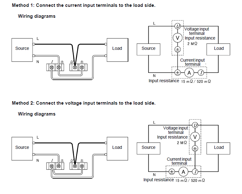
Moving beyond the basic meter base, power meters are often used for more detailed analysis and monitoring of electrical consumption. Unlike a standard utility meter, which simply measures total energy usage, a power meter can provide information about voltage, current, power factor, and other parameters. This makes them incredibly useful for troubleshooting electrical problems, optimizing energy efficiency, and managing electrical loads.
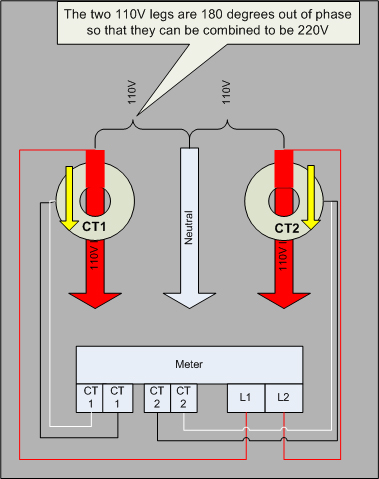
The diagram shows how a power meter is connected to a circuit to measure these parameters. You'll typically see current transformers (CTs) and voltage leads connected to the circuit being measured. The CTs are used to measure the current flowing through the wires without directly connecting the meter to the high-voltage conductors. Instead, the CT induces a small current in the meter proportional to the current in the main wire. The voltage leads, on the other hand, directly measure the voltage of the circuit.
The power meter then uses the voltage and current measurements to calculate power consumption and other related values. By analyzing these measurements, you can identify areas where energy is being wasted, diagnose electrical problems, and optimize the performance of electrical equipment. Power meters are commonly used in industrial settings, commercial buildings, and even some residential applications to monitor energy usage and improve energy efficiency. Understanding how these meters are wired and how they function is essential for anyone involved in electrical engineering or energy management.
These diagrams serve as visual aids to better understand the journey of electricity into our lives. From the main connection to detailed monitoring, wiring diagrams are valuable assets to deepen the grasp of power distribution and measurement.
If you are looking for Electric Meter Wiring Diagram you've came to the right page. We have 25 Pics about Electric Meter Wiring Diagram like Electric Meter Box Wiring Diagram Uk - Wiring Diagram, Electric Meter Wiring Diagram and also Electric Meter Wiring Diagram - Jatam Bila. Read more:
Electric Meter Wiring Diagram
 stewart-switch.com
 House Wiring Diagram With Energy Meter - Wiring Boards
 www.wiringboards.com
 Power Meter Wiring Diagram - Wiring Diagram
wiringdiagram.2bitboer.com wiring hioki
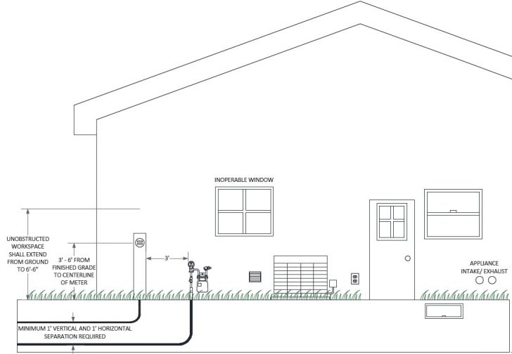
Meter Installation Guidelines | We Energies - Electric Meter Wiring
 2020cadillac.com
 meter wiring energies underground mounting requirements locations
Single Phase Electric Meter Wiring Diagram
 www.circuitdiagram.co
 Electric Meter Wiring Diagram
 mungfali.com
 House Wiring Diagram With Energy Meter - Wiring Boards
 www.wiringboards.com
 Wiring Diagram Of 3 Phase Electric Meter - Circuit Diagram
 www.circuitdiagram.co
 Electric Meter Wiring Diagram
 stewart-switch.com
 [DIAGRAM] Wiring Electric Meter Diagram - MYDIAGRAM.ONLINE
![[DIAGRAM] Wiring Electric Meter Diagram - MYDIAGRAM.ONLINE](https://lh3.googleusercontent.com/blogger_img_proxy/AEn0k_vrSJFA27jG1x3H5K-VSR3U3qUK9vSGRDaNT9yo6_JdUjPzMlp3D_RlsfEreHxii9Ls7mG_wjC-uGEAaN0p40EdPw65rYbEiRiiSSqTZsnGp6Q8QtJYSVl2XqH2PH4_UMnz5rcAf3FD5n52qfYlBJX1Nc_82UAnpuskaej8maLXvWEx3DFIhhvA-hyVtMI6=s0-d) mydiagram.online
mydiagram.online Electric Meter Wiring Diagram
 mungfali.com
 Electric Meter Base Wiring | Wiring Diagram - Electric Meter Wiring
 2020cadillac.com
 wiring ansi socket power 100a
House Wiring Diagram With Energy Meter - Wiring Boards
 www.wiringboards.com
 Electric Meter Wiring Diagram
 mungfali.com
 Electric Meter Wiring Diagram
 stewart-switch.com
 Electric Meter Wiring Diagram
 stewart-switch.com
 Electric Meter Wiring Diagram - Jatam Bila
 jatambila.blogspot.com
 Electric Meter Box Wiring Diagram Uk - Wiring Diagram
Power Meter Wiring Diagram - Wiring Diagram
 wiringdiagram.2bitboer.com
 meter wiring
[DIAGRAM] Wiring Electric Meter Diagram - MYDIAGRAM.ONLINE
![[DIAGRAM] Wiring Electric Meter Diagram - MYDIAGRAM.ONLINE](https://lh3.googleusercontent.com/blogger_img_proxy/AEn0k_s9fZZfyI6uYo918DM3iF4HELMrZGV6fKfxjWX7FjrnDTnXLeR1VsdkkO-Eu66V0xaKOSPZkjoEggmP5B_Y2gJN4SUhdnxCsCKEhuhBTG3_TajkjPQPXhfjcjF7azlnsCJPqj-mecAsbc0VFY6DXKF0HMmbBQbkPA9mv31gR2Cflq3xYg=s0-d) mydiagram.online
mydiagram.online [DIAGRAM] Electric Meter Box Wiring Diagram Uk - MYDIAGRAM.ONLINE
![[DIAGRAM] Electric Meter Box Wiring Diagram Uk - MYDIAGRAM.ONLINE](https://c8.alamy.com/comp/E0435D/a-domestic-electricity-meter-housed-in-an-external-box-scotland-uk-E0435D.jpg) mydiagram.online
mydiagram.online Electrical Meter Base Wiring Diagram - Wiring Diagram
wiringdiagram.2bitboer.com [DIAGRAM] Electric Meter Box Wiring Diagram Uk - MYDIAGRAM.ONLINE
![[DIAGRAM] Electric Meter Box Wiring Diagram Uk - MYDIAGRAM.ONLINE](https://lh3.googleusercontent.com/blogger_img_proxy/AEn0k_sdjdYHk7D4TvFQzpD5JLgFVnga2G3xDgdGF0AZ0FNs6a96z9rGiR5J-oBpa4BSAWIOOTYSHqw-Rt7TkMDKiLMcrh1g9aukrIS0Ly7YC7Z4I35swFM39iWYqR21AENc=s0-d) mydiagram.online
mydiagram.online Electric Meter Wiring Diagram
 stewart-switch.com
 Electric Meter Schematic - Wiring Diagrams Hubs - Electric Meter Wiring
 2020cadillac.com
 wiring hubs
Meter wiring. Meter wiring energies underground mounting requirements locations. House wiring diagram with energy meter